Federal
Corelight accelerates OMB logging adoption
If you missed the Office of Management and Budget memo M-21-31, let me provide you the information that you need to know if you are in the federal...
One of the most popular and regularly occurring questions I see in network security monitoring forums involves how to instrument a small office – home office (SOHO) environment. There are ways to accomplish this goal. For example, I instrument my home using techniques explained in this post. However, accomplishing this goal involve architectural and privacy concerns that must be addressed before any security analyst sees SOHO traffic.
The requirement for which we are architecting this solution is as follows:
Identify a single location in the network to instrument with a network tap or switch span port that provides the maximum visibility. This means seeing all devices on the network, with a strong preference for identifying devices by source IP address.
Note that I do not consider it important in this scenario to see traffic that is blocked by the ISP equipment. I am more concerned with traffic originating from customer devices such as laptops, mobile devices, Internet of Thing (IoT) systems, and the like.
Let’s begin with a look at the equipment and architecture available in most SOHO setups.
Figure 1 depicts the standard SOHO network architecture. Letters A-D are possible monitoring locations, to be discussed below.
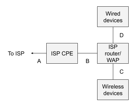
Most home users and many small office environments are connected to the Internet via customer premise equipment (CPE) provided by their Internet service provider (ISP). This box may or may not be available or visible to the customer. In the context of a system like Verizon FIOS, for example, the ISP CPE is the box attached to the outside of a residence, with a warning that only Verizon technicians should open it.
The ISP also provides a gateway device that provides routing and wireless access point (WAP) functionality. This is the piece of equipment familiar to most home and small office users. It typically has a gigabit copper Ethernet connection that connects to the ISP CPE, on its wide area network (WAN) side, and four gigabit copper Ethernet ports for devices on its local area network (LAN) side. Customer devices gain network access via WiFi to the ISP WAP or via copper Ethernet cables to the embedded switch on the same device.
On the WAN side of the router, the device usually has a public IP address provided by the ISP. This may not necessarily be the case, however. On the LAN side of the router, the device provides RFC 1918 private addresses, often in the 192.168.0.0/16 subnet. The router acts as a gateway, using network address translation (NAT), or for the more strictly minded, network port address translation (NPAT), so that client devices share a single IP address provided by the ISP. (Note that in some situations, multiple residences even share the same public IP address, and differentiate between each other via the port range. That is not considered in this post as it is extraneous to the discussion.)
Now, where does one monitor, given this architecture?
Location A is off limits to the customer. It is likely a cable exiting the ISP CPE and entering the ground.
Location B is a possibility, assuming the cable between the ISP CPE and router is a copper Ethernet cable. One could insert a reliable network tap (typically outside the home user’s budget) or a decent small managed switch with a span port (like a Netgear GS30Xe model).
However, and this is crucial: because of the NAT done by the router, all traffic will appear to originate from a single IP address. Whether the customer has 100 devices or 1 device, they will all share the single IP address. This reality makes it much more difficult for a security analyst to track down the originator of suspicious or malicious network traffic.
Location C is essentially not possible. Yes, there are various penetration testing tools and wireless network troubleshooting tools that can try to access WiFi traffic. However, they do not expose the traffic in a form usable to security analysts, assuming that the WiFi protocols in use are at all modern.
Location D is a possibility, assuming that the user installs a network tap or switch span port as in location B. Still, how many of us use wired Ethernet these days? My lab has wired devices, but all of the consumer devices processing the most sensitive data access the Internet via WiFi. Only monitoring at location D would ignore WiFi traffic.
In other words, the standard SOHO network architecture is not well-suited for network security monitoring, because there isn’t a good place, by default, to see the originating IP addresses, which are generally needed to investigate suspicious and malicious activity.
Figure 2 depicts the sort of setup one needs if visibility is designed into the architecture, rather than added as an afterthought.
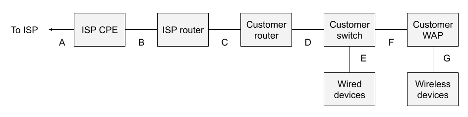
The major changes include the following:
Don’t be fooled into thinking that one need only buy a new combination router/WAP. It’s essential to split these functions. Consumer-grade customer routers do not offer span ports, which cheap consumer-grade network switches do. This architecture takes advantage of that fact in order to provide suitable monitoring locations.
Let’s review the options.
The bottom line is that the location D is the best monitoring location, assuming that the customer WAP is not doing NAT. If the customer WAP is acting as a router with NAT, then all of the wireless devices will have the same source IP address as seen in location D.
In an architecture designed for visibility, introducing a network tap, or simply spanning the uplink from the network switch, at point D, satisfies the visibility requirement.
Some of you may ask if it’s possible to simplify the previous architecture. It is:
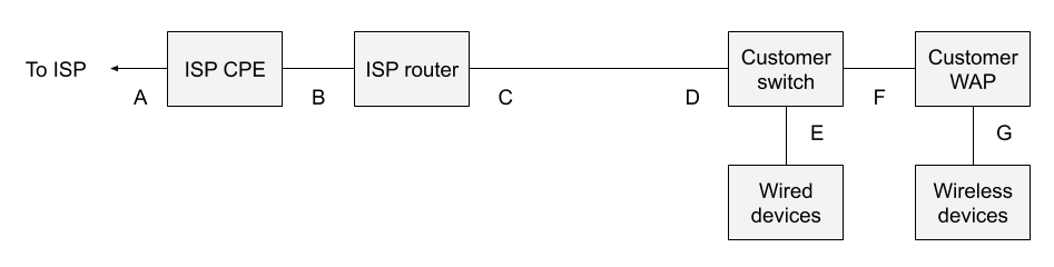
Here I’ve removed the customer router between monitoring points C and D. I prefer to introduce my own customer router, as I consider any device managed by the ISP to be untrustworthy. I don’t have any particular concern about my ISP, but I want to enforce my own firewall rules on a gateway I own. It is possible to run without the customer-owned router, but that’s a decision for security and network/system administrators to make.
It is possible to conduct network security monitoring with tools such as Corelight and Zeek in SOHO environments, but in order to satisfy the visibility requirements one must have a compatible architecture. Otherwise, one ends up monitoring in a location like point B in Figure 1. Yes, one can see traffic from the SOHO network to the Internet at that point, but because it all shares the same public IP address, it is difficult to identify the originator of the traffic. The analyst can tell that something is happening, but not necessarily who is affected. If one wants to seriously introduce NSM into SOHO, and incidentally accept the privacy and other policy considerations associated with monitoring home users, then it pays to introduce a few more network elements and build visibility in.
If this is all too much for the average security architect, then it might be simpler to enforce a VPN policy on company equipment that routes all work from home traffic to the corporate VPN concentrators. If the network juncture from the VPN concentrator to the corporate network was not already instrumented, then introducing a specific NSM device at that location will pay dividends.
The architecture depicted in this post is most likely going to be adopted by home power users who want to see their network in all its grandeur. It is also a viable solution for organizations that provide dedicated lines and equipment for VIPs, and who provide IT support to those VIPs as a requirement for their business operations.
Good luck with your SOHO NSM journey!